Products
Qantur
Ansys Motion
Multibody Dynamics Simulation Software
Robust Multibody Dynamic System Design with Ansys Motion
- Car
- Drivetrain
- Links
- EasyFlex
Features
Quick Specs
Still have a question?
Multibody Dynamics Analysis
Drivetrain Toolkit
FE Dynamics
MATLAB Interface
Car Toolkit
EasyFlex Toolkit
API Development
SMP and MPP
Links Toolkit
Linear
Modal Flex
Parametric Gear Creation
Libraries of Bearings
Capabilities
Ansys Motion Is A New Paradigm in Flexible Multibody Dynamics (MBD)
Capabilities
Key Features
Solver

The Motion solver can accelerate the simulation speed for large degree of freedom systems.
Simulate faster using shared memory parallel processing (SMP) and massive parallel processing (MPP) environments.
Pre-post Processor

Ansys Motion pre-processor provides an optimized modeling environment for components and systems.
Components can be modeled as a single entity consisting of a part file and a mesh file. Part files and mesh files are treated and managed independently, allowing for data reuse in other models.
Post-processor provides fast animation of a system consisting of complicated geometries.
MBD Pro

MBD Pro is included in the Ansys Motion base package and is a module to analyze rigid body systems.
The governing equations of motion are formulated based on a parametric generalized coordinate system. The rigid bodies are connected by joints, primitive constraints, bushings, contacts and user-defined function expressions. Smooth surface-to-surface contact is supported. The surface can be represented by piecewise triangular patches or a NURBS surface.
FE Dynamics

Perform dynamic analysis of a mixed system of rigid and flexible bodies.
The solver was originally designed to contain the two different disciplines of MBD and finite element (FE) analysis. Therefore, there are many unique connecting elements of rigid and flexible bodies. Since the numerically stable implicit integration method is used, the solution is free from numerical noise and very smooth and reliable.
Modal Flex

When a flexible body has no contact or mildly changing force elements, the modal flexible body is preferred due to its efficiency.
Mode shapes are extracted from a finite element program such as Ansys Mechanical and deformation is expressed by the linear combination of the mode shapes. Since it solves reduced modal coordinates, the computation time is short. Modal flexible body and full nodal flexible body can be switched easily and can be solved with other rigid and nodal flexible bodies.
Linear

Linear analysis is used to solve eigenvalues and eigenvectors of FE bodies, EasyFlex bodies or systems.
Natural frequencies and modes can be simulated. For the body eigenvalue analysis, the static correction mode will deliver a more accurate solution of a modal flexible body.
Fatigue

Conventional fatigue analysis has required two independent analyses of load history and stresses.
These two processes are combined as one in the Ansys Motion fatigue analysis system. The Ansys Motion solver generates the load history and stress history at the same time. The fatigue life can be directly visualized in Ansys Motion post-processor.
MATLAB Interface

Included in Ansys Motion base package, MATLAB/Simulink interface allows co-simulation of MATLAB control model and Ansys Motion mechanical models.
System input/output in the Ansys Motion model and Simulink file in MATLAB must be defined.
FMI

A functional mockup interface (FMI) capability facilitates co-simulation of an Ansys Motion mechanical model with other simulation tools that support FMI.
System input/output in the Ansys Motion model must be defined. Ansys Motion’s FMI is only available as a slave simulator.
Drivetrain Toolkit

Ansys Motion Drivetrain toolkit can analyze the noise, vibration and harshness (NVH) characteristics of drivetrain systems under variable driving conditions.
It can conduct analyses from the initial design concept through to detailed production models. Waterfall color maps and order tracking data can be produced in the same manner as in a real-world test environment to allow easy comparison of simulation and reality.
Links Toolkit for Chains and Belts

An Ansys Motion Links toolkit analysis consists of path bodies (wound bodies) and segment bodies (winding bodies).
Once the path and segment bodies are defined, a chain assembly is automatically created. Path and segment bodies can be a subsystem, part or mesh files. This allows a user to build various types of irregular chains. One window controls all the contact parameters among the segment and path bodies. Connections between two segments can be any kind of force, joint or contact entity.
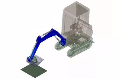
Links Toolkit for Tracks
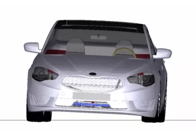
Predefined geometries for segment and path bodies are provided so that a parametric study is possible.
Track assembly is further simplified to eliminate the picking step of path bodies. The path bodies are automatically searched and used to automatically assemble the track segments. Contact surfaces are automatically defined for the predefined geometries so that contact surfaces do not need to be defined. The predefined geometries have complicated modeling details to represent the real shapes.
Car Toolkit

Dedicated template and subsystem modeling tools can be used to build chassis, suspension, steering and wheels for predefined analysis scenarios.
Symmetric modeling capabilities and template-based workflows allow users to easily analyze kinematics and compliance (K&C) and ride and handling (R&H) scenarios.
EasyFlex Toolkit

Unlike conventional finite element analysis, the Ansys Motion EasyFlex toolkit does not require meshing prior to structural analysis.
Since the meshing of complex 3D CAD is not needed, it makes flexibility modeling available to all users, even those unfamiliar with meshing technologies. By using the Ansys Motion EasyFlex toolkit, the strain and stress of machine parts with various shapes can be calculated within minutes.
Translators

A user-friendly interface with a wide range of tools, wizards, and visualizations to assist engineers in the design and analysis process.
Other CAD data files must be translated through the corresponding CAD translator.
Visioneering
Recent Events &
Webinars
Discover how engineering simulation is expanding across the entire product lifecycle.
Ansys Multiphysics
Conference
Join us on Saturday, June 10th, 2023, at 3 PM. The event will take place at Riverside Park, 123 River Lane, Springfield.
Blog
Future Tech Expo 2025
Join us on Saturday, June 10th, 2023, at 3 PM. The event will take place at Riverside Park, 123 River Lane, Springfield.

Blog
Innovative Simulations
Summit 2025
Join us on Saturday, June 10th, 2023, at 3 PM. The event will take place at Riverside Park, 123 River Lane, Springfield.

Innovative Simulations
Summit 2025
Join us on Saturday, June 10th, 2023, at 3 PM. The event will take place at Riverside Park, 123 River Lane, Springfield.
Ansys Multiphysics
Conference
Join us on Saturday, June 10th, 2023, at 3 PM. The event will take place at Riverside Park, 123 River Lane, Springfield.
Blog
Innovative Simulations
Summit 2025
Join us on Saturday, June 10th, 2023, at 3 PM. The event will take place at Riverside Park, 123 River Lane, Springfield.

Visioneering
Qantur Blogs &
Trends
Discover how engineering simulation is expanding across the entire product lifecycle. engineering / product design analysis by modeling & simulation.

Innovative Simulations Summit 2024
Introduction Mi tincidunt elit, id quisque ligula ac diam, amet. Vel etiam suspendisse morbi eleifend faucibus eget vestibulum felis. Dictum quis montes, sit sit. Tellus aliquam enim urna, etiam. Mauris

Ansys Multiphysics Conferences
Introduction Mi tincidunt elit, id quisque ligula ac diam, amet. Vel etiam suspendisse morbi eleifend faucibus eget vestibulum felis. Dictum quis montes, sit sit. Tellus aliquam enim urna, etiam. Mauris

Ansys Multiphysics Conferences
Introduction Mi tincidunt elit, id quisque ligula ac diam, amet. Vel etiam suspendisse morbi eleifend faucibus eget vestibulum felis. Dictum quis montes, sit sit. Tellus aliquam enim urna, etiam. Mauris

Innovative Simulations Summit 2024
Introduction Mi tincidunt elit, id quisque ligula ac diam, amet. Vel etiam suspendisse morbi eleifend faucibus eget vestibulum felis. Dictum quis montes, sit sit. Tellus aliquam enim urna, etiam. Mauris
Innovate
Breaking News & White Paper
Discover how engineering simulation is expanding across the entire product lifecycle.

Smart Strategies for Large Structural Simulations
One way to gauge the progress of engineering simulation software is through the lens of size. Engineers today routinely run structural simulations with a few million degrees of freedom, and the largest commercial structural simulations have topped even 100 million degrees of freedom.
Introduction Mi tincidunt elit, id quisque ligula ac diam, amet. Vel etiam suspendisse morbi eleifend faucibus eget vestibulum felis. Dictum quis montes, sit sit. Tellus
Services
Qantur Case Studies
Qantur Technologies is a pioneer engineering simulations company based in Gurgaon –India. We provides expert Computer Aided Engineering – CAE consulting services for engineering / product design analysis by modeling & simulation.
Transform Ideas into Reality—Explore Our Simulation Solutions Today!
Partner with Us to Revolutionize Engineering Excellence!
Testimonials